
Home »
Pneumatic Actuator Systems: The Ultimate Guide
Table of Contents
- What Are Pneumatic Actuator Systems
- How Pneumatic Actuator Systems Work: The Operating Principle
- Types of Pneumatic Actuators and Their Applications
- Pneumatic vs. Electric Actuators: Strengths and Trade-offs
- System Sizing and Actuator Selection Calculations
- Controls, Instrumentation, and Failure Prevention
- Why Pneumatic Systems Dominate Industrial Automation
- Frequently Asked Questions
Last Updated: October 17, 2026
What Are Pneumatic Actuator Systems
A pneumatic actuator system is a mechanical device that converts compressed air energy into controlled linear or rotary motion to operate valves, gates, and industrial equipment.
The global pneumatic valve actuators market reflects this dominance, with Spherical Insights projecting growth from USD 5.08 billion in 2025 to USD 11.23 billion by 2035.
Pneumatic actuator systems are valued for their simplicity: compressed air, a control valve, and an actuator create a complete automation loop, with no complex wiring, no electrical hazards in explosive atmospheres, and no motor-bearing maintenance.
How Pneumatic Actuator Systems Work: The Operating Principle
The operating principle of pneumatic actuator systems rests on a single concept: pressurized air pushes a piston inside a cylinder, creating mechanical force that moves a shaft connected to a valve stem, rotating a ball, butterfly, or plug to control fluid flow.
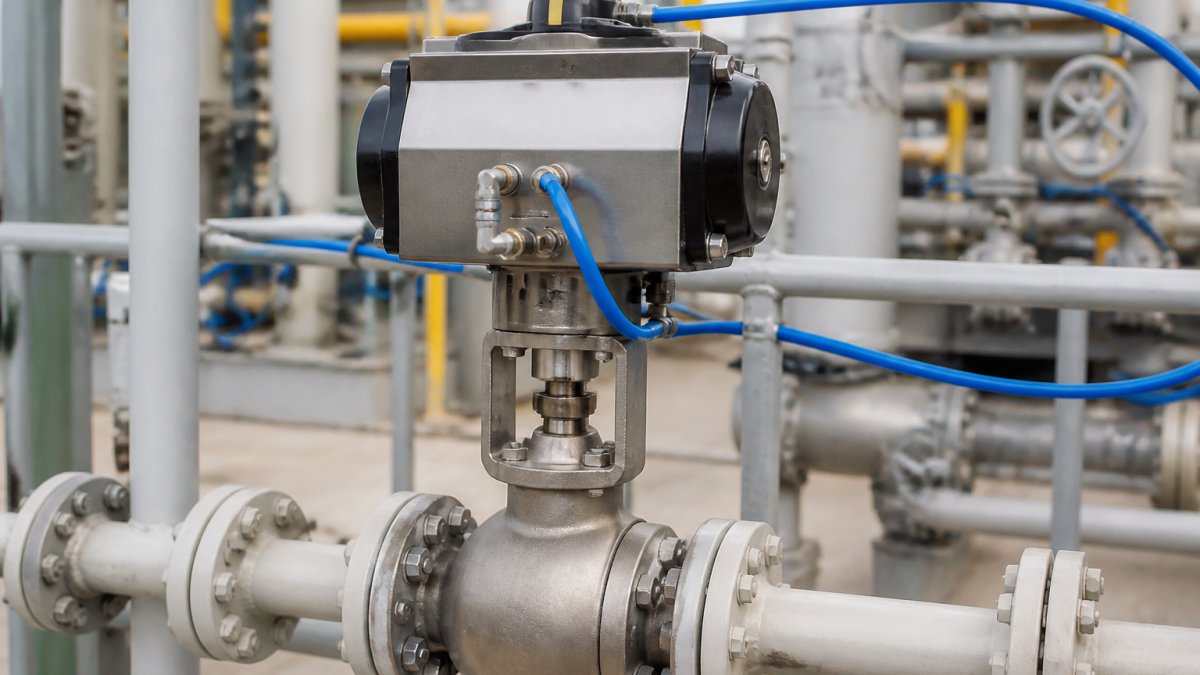
Compressed Air as the Energy Source
Compressed air is the fuel of pneumatic actuator systems. Air enters a facility through a compressor, travels through piping, and reaches the actuator through control valves that direct flow to specific chambers.
Quality matters here. Moisture, oil contaminants, and particulates degrade seals and reduce actuator lifespan, so a proper air supply system includes dryers, filters, and regulators. Many facilities overlook air quality, then blame the actuator for failure when the real culprit is contaminated supply.
Core Components: Piston, Shaft, Housing, and Valve Integration
Every pneumatic actuator system contains four critical elements working in concert. The piston is the moving part inside the cylinder that responds to air pressure. The shaft (or rod) extends from the piston and connects mechanically to the valve.
These components must be precisely matched: a piston sized too small cannot generate required force, a housing too thin cannot safely contain pressure, and seal materials must resist the specific fluids in your system.
Types of Pneumatic Actuators and Their Applications
Single-Acting vs. Double-Acting Actuators
Single-acting pneumatic actuators use air pressure to move the piston in one direction; a spring returns it when pressure releases.
Double-acting pneumatic actuators use air pressure to move the piston in both directions. Air enters one chamber to extend, then enters the opposite chamber to retract.
Single-acting is inherently safer; double-acting is more versatile. Most refineries and chemical plants use double-acting actuators because they need rapid, repeatable valve positioning throughout operation.
Linear Motion and Rotary Motion Actuators
Linear pneumatic actuators (cylinders) extend and retract in a straight line, ideal for sliding gates, dampers, or any application requiring push-pull motion. A piston moves forward and back inside a cylinder; the shaft translates that motion directly to the load.
Rotary motion actuators convert linear piston motion into rotational force (torque), turning a shaft through a fixed angle, typically 90 degrees for valve actuation. Rotary actuators are standard for ball valves, butterfly valves, and plug valves because they deliver the torque needed to overcome friction and seat the valve tightly.
For most valve applications, you’ll use a rotary pneumatic actuator; linear actuators appear in auxiliary functions like opening access hatches, positioning dampers, or operating mechanical linkages.
Pneumatic vs. Electric Actuators: Strengths and Trade-offs
Speed, Power, and Efficiency Comparison
Pneumatic actuator systems are faster than electric motors: a pneumatic actuator responds in milliseconds, while an electric motor takes seconds to accelerate and decelerate. That speed advantage matters where rapid valve response prevents overpressure, runaway reactions, or safety hazards.
Electric actuators deliver higher overall efficiency, they convert electrical energy into mechanical motion with less waste heat. According to research by J. Markowski in MDPI, overall pneumatic system efficiency often does not exceed 30%, though targeted improvements can reduce air consumption by up to 70%.
Power-to-size ratio favors pneumatics: a small pneumatic actuator generates substantial force, while an electric motor of equivalent size is weaker. Pneumatic actuator systems are also lighter and more compact than equivalent electric systems.
Cost and Maintenance Considerations
Pneumatic actuator systems cost less upfront than electric alternatives. The components are simpler, manufacturing is straightforward, and installation requires no electrical expertise or permits.
Maintenance differs fundamentally. Pneumatic actuators have no brushes, bearings, or complex gearboxes; seal replacement every few years is typical, while electric motors require bearing lubrication, winding inspection, and eventual rewinding.
However, compressed-air generation costs money. Running a compressor 24/7 consumes significant energy. Over a decade, electric actuators may cost less to operate despite higher initial purchase price.
System Sizing and Actuator Selection Calculations
Determining Force, Stroke, and System Pressure Requirements
The fundamental equation is Force = Pressure × Piston Area. If your valve requires 500 pounds of force and your system runs at 100 PSI, you need a piston with an effective area of 5 square inches.
Stroke length determines cylinder bore size, and the mounting method (front, rear, or trunnion) affects how the actuator connects to your valve and influences space requirements.
Most engineers consult actuator selection tables or software that cross-references force, stroke, and pressure to recommend cylinder bore size.
Air Supply Quality and System Design Fundamentals
Clean, dry, regulated air is non-negotiable. Moisture corrodes internal seals and creates rust inside cylinders, oil carryover gums up seals and reduces responsiveness, and particulates scratch piston surfaces and cause leakage.
A proper air-supply system includes:
- Aftercooler: Removes heat from compressed air, reducing moisture content
- Dryer: Eliminates remaining water vapor using desiccant or refrigeration
- Filter: Removes particles and residual oil
Piping matters too. Undersized lines create pressure drop and slow response, corrosion inside steel pipes releases particles, and every connection point is a potential leak source. Copper or stainless-steel tubing resists corrosion, and proper design minimizes connections and uses quality fittings.
Controls, Instrumentation, and Failure Prevention
Directional Control Valves and On/Off vs. Modulating Control
The directional control valve is the brain of your pneumatic actuator system. It routes compressed air to extension and retraction chambers, determining actuator motion.
On/off control is binary: the valve is fully open or fully closed. Most ball valves, butterfly valves, and plug valves use on/off control because the valve itself has only two stable positions.
Modulating control allows the actuator to stop at any intermediate position, useful for flow-control valves, dampers, or applications requiring variable throughput.
Safety, Fail-Safe Behavior, and Maintenance Protocols
Pneumatic actuator systems are inherently safer than electric systems in explosive atmospheres because compressed air cannot ignite.
Pressure relief valves protect against overpressure, shuttle valves prevent backpressure damage, and check valves isolate piping sections.
Maintenance prevents failure. Inspect seals annually. Change air filters quarterly. Drain moisture from the system monthly.
Research from Springer Nature on monitoring pneumatic actuator behavior highlights the value of early fault detection.
Why Pneumatic Systems Dominate Industrial Automation
Pneumatic actuator systems dominate because they solve real problems that electric systems struggle with. In oil and gas refineries, where explosive atmospheres are routine, pneumatics are non-negotiable.
Speed matters too. A pneumatic actuator responds in 50 milliseconds; an electric motor takes 500.
Cost-effectiveness seals the case. Facilities with existing compressed-air systems can add pneumatic actuator systems at minimal capital cost.
The market growth reflects this reality.
When your facility requires pneumatic actuator systems engineered to exact specifications, Valtorc International delivers. Whether you need single-acting fail-safe designs, double-acting proportional systems, or complete integrated packages, we size, test, and deliver solutions that perform under the toughest conditions. Contact Valtorc International for a detailed quote and discover how our custom-engineered pneumatic actuator systems can eliminate downtime and maximize operational reliability across your facility.
Frequently Asked Questions
How does a pneumatic actuator system work?
Pneumatic actuator systems convert compressed air energy into mechanical motion. Air pressure enters the actuator’s housing, pushing the piston along the shaft to create linear or rotary motion. A directional control valve directs air flow in and out of the system, controlling the direction and speed of actuation. The spring-return mechanism in single-acting models returns the piston to its original position when air pressure is released. This fast-response design makes pneumatic systems ideal for repetitive industrial applications requiring quick on/off control.
What are the main types of pneumatic actuators?
Pneumatic actuators fall into two primary categories: single-acting and double-acting. Single-acting actuators use a spring to return the piston to its rest position, making them simpler and more cost-effective for basic applications. Double-acting actuators use pressurized air on both sides of the piston for movement in both directions, offering greater force and control. Additionally, actuators are classified by motion type: linear pneumatic cylinders produce straight-line motion, while rotary actuators generate rotational force. Each type serves specific industrial machinery, building automation, and HVAC control applications.
How do you size a pneumatic actuator for your application?
Sizing requires calculating three key parameters: required force, stroke length, and system pressure. First, determine the force needed to move or control your valve or load. Next, measure the distance the piston must travel (stroke). Then, confirm your system pressure rating, typically 80-100 PSI in most industrial settings. Use the formula: Force = Pressure × Piston Area to verify the actuator can deliver sufficient force. Consider response time and mounting requirements (front or rear mounting) to ensure compatibility with your valve body and control system. Undersizing reduces performance; oversizing increases air consumption and cost.
What is the difference between pneumatic and electric actuators?
Pneumatic actuators excel in speed and simplicity; they respond in milliseconds and require minimal maintenance. Electric actuators offer precise modulating control and lower long-term energy costs in stationary applications. Pneumatic systems work reliably in hazardous environments (non-combustible, intrinsically safe) and are lightweight, making them ideal for mobile or space-constrained applications. However, pneumatic systems typically operate at 30% overall efficiency or less, while electric actuators can exceed 80% efficiency. Electric actuators cost more upfront and require more complex wiring but eliminate compressed-air infrastructure costs. Choose pneumatic for fast, simple on/off control; choose electric for precision, efficiency, and quiet operation.
What are the advantages and disadvantages of pneumatic actuators?
Advantages include fast response time, simple design, low cost, non-combustible operation in hazardous areas, and minimal maintenance. Pneumatic systems are lightweight, adaptable to extreme temperatures, and safe around flammable materials. Disadvantages include lower overall efficiency (often under 30%), higher air consumption, noise generation, and the need for clean, dry compressed air. Air leakage can reduce system performance, and pressure loss over long distances affects force delivery. For applications requiring high precision or continuous modulating control, electric or hydraulic alternatives may be more suitable. However, for rapid cycling, on/off applications, and environments where safety and simplicity matter most, pneumatic systems remain unmatched.
How do you maintain a pneumatic actuator system?
Regular maintenance ensures reliable performance and extends service life. Monitor air supply quality: use filters to remove contaminants, dryers to eliminate moisture, and regulators to maintain consistent pressure. Inspect the actuator housing, piston rod, and mounting points for leaks or corrosion. Lubricate moving parts according to manufacturer specifications, using only pneumatic-grade lubricants. Check directional control valves and solenoid valves for proper operation. Replace seals if you notice air leakage or sluggish response. In high-temperature or high-pressure applications, inspect more frequently and consider fail-safe valve configurations. Preventive maintenance reduces downtime and prevents costly failures in critical industrial machinery.
What should you consider when selecting a pneumatic actuator?
Start with your application’s force and stroke requirements, then verify system pressure compatibility. Determine whether you need single-acting (simpler, lower cost) or double-acting (greater control) operation. Choose linear actuators for straight-line valve movement or rotary actuators for rotating ball valves and butterfly valves. Consider mounting orientation (front or rear) to fit your valve body and pipeline layout. Evaluate response time: fast-response actuators suit high-speed production lines, while slower models work for less demanding processes. Assess air supply quality and system design capacity, if your facility lacks adequate compressed air infrastructure, upgrading may be necessary. Finally, confirm certifications for your industry.
Can pneumatic systems reduce energy consumption?
Yes, but only with proper system design and maintenance. A 2026 study reports that overall pneumatic system efficiency often does not exceed 30%, yet targeted improvements can reduce air consumption by several tens of percent, and in some cases by up to 70%. Key strategies include upgrading to efficient actuators, minimizing air-line length and diameter, reducing pressure to the minimum required level, and eliminating leaks. Installing flow-control valves and pressure regulators optimizes performance per application. Regular maintenance, replacing worn seals, cleaning filters, and draining moisture, prevents waste. While pneumatic systems will never match electric-actuator efficiency in stationary applications, proper engineering and maintenance can significantly lower operating costs and environmental impact.

CREDIT APPLICATION
Please fill out our credit application for purchase orders and net terms. Download here

DISTRIBUTORS WANTED
Apply to become an official protected distributor. Click here to fill out our distributor application. (Online Form)

VALVE PRODUCT CATALOG
New! Download our 2018 product overview catalog or call us to request a copy. Click here to download (PDF)


