
Home »
Industrial Valve Seat Leakage: Classes & Testing
Table of Contents
- What Is Valve Seat Leakage and Why It Matters
- Understanding FCI 70-2 Seat Leakage Test Standards
- Valve Seat Leakage Classifications: Class I Through Class VI
- Valve Seat Leakage Testing Procedure: How Standards Are Verified
- Signs of a Bad Valve Seat: Detection and Failure Causes
- Metal-Seat Versus Soft-Seat Performance Under Leakage Stress
- Selecting the Right Leakage Class for Your Application
- Frequently Asked Questions
Last Updated: October 14, 2026
What Is Valve Seat Leakage and Why It Matters
Valve seat leakage is the unintended flow of fluid past a closed valve’s seating surfaces.
The global industrial valve market is valued at USD 88.6 billion in 2026 and is projected to reach USD 134.8 billion by 2036, a 4.3% compound annual growth rate (Future Market Insights valve market analysis).
Leakage isn’t binary; a small weep acceptable in one application may be unacceptable in another. Understanding classifications, test standards, and failure modes helps you choose the right valve.
Industrial valve seat leakage is measured and classified by standard test procedures. The right leakage class depends on your service conditions, not on generic “best practices.”
Understanding FCI 70-2 Seat Leakage Test Standards
The FCI 70-2 standard, published by the Fluid Controls Institute, defines how to measure and classify valve leakage, specifying test procedures, allowable rates, and acceptance criteria for industrial control valves.
FCI 70-2 establishes six leakage classes, Class I through Class VI, each with progressively tighter shutoff requirements, and defines the test medium, pressure, temperature, and acceptable rates.
A valve is pressurized on one side of the seat while the other is monitored, at the rated pressure differential and temperature for each class.
One critical point: FCI 70-2 control valve leakage classes comparison emphasizes that test medium, pressure, temperature, valve size, and allowable leakage must all be considered together.
Comparing leakage test results without matching test conditions is meaningless. Always verify that pressure, temperature, and test fluid match your actual service conditions.
Valve Seat Leakage Classifications: Class I Through Class VI
The six leakage classes form a hierarchy from bubble-tight shutoff to minimal leakage, each with specific allowable rates and test conditions.
Class I and Class II: Bubble-Tight Performance
Class I is the tightest shutoff available, permitting no visible leakage, not even a single bubble underwater.
Class II allows only microscopic leakage: a few drops per minute at rated pressure.
Both classes demand precision manufacturing and frequent inspection.
Class III and Class IV: Industrial Standard Shutoff
Class III allows up to 0.5 cubic inches per minute (in³/min) of leakage at rated conditions, typical for general industrial shutoff where some leakage is acceptable but controlled.
Class IV tightens that to 0.1 in³/min, ten times less than Class III.
Both classes are achievable with well-designed metal seats and proper installation; the difference is manufacturing tolerance and seat geometry, with Class IV lapped and tested to tighter tolerances.
Class IV vs Class VI Valve Leakage: Where They Differ
Class IV allows 0.1 in³/min; Class VI allows only 0.01 in³/min, a tenfold reduction, but the practical differences run deeper.
Class VI valves are engineered for critical shutoff. They require precision-ground metal seats, specialized materials, and rigorous testing, so they cost significantly more than Class IV.
Class IV handles most industrial shutoff needs at a fraction of the cost.
The decision point is whether leakage poses a safety or environmental risk: if it does, move to Class VI; if not, Class IV is the practical choice.
Class V and Class VI: Minimal Leakage for Critical Applications
Class V allows 0.01 in³/min of leakage, used where leakage must be minimized but some loss is tolerable.
Class VI is the tightest standard: 0.001 in³/min or less, bubble-tight performance for metal-seated valves; the cost and complexity are significant, but the safety margin justifies it.
Both classes demand metal-to-metal seats with precision lapping.
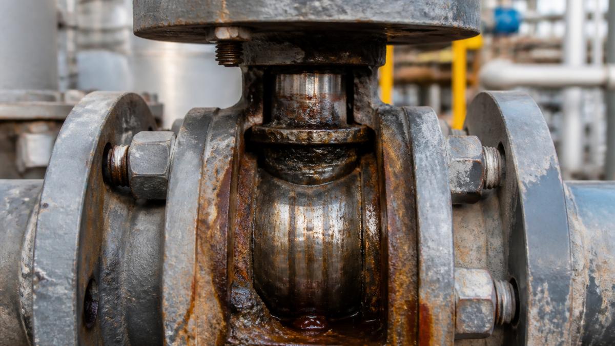
Valve Seat Leakage Testing Procedure: How Standards Are Verified
Testing follows a standardized protocol so results are reproducible across vendors and labs. The valve is mounted in a test rig, pressurized on one side of the seat, and monitored on the other at the pressure differential, temperature, and fluid type specified for the target class. The math that turns a raw measurement into a pass/fail verdict separates a credible test from a marketing claim.
Step-by-step test sequence
- Mount and orient the valve in the closed position, with test pressure applied to the side that sees pressure in service.
- Stabilize temperature. Bring the valve and test fluid to the specified temperature before pressurizing; a cold valve tested hot will not reproduce service leakage.
- Apply the rated differential. Hold pressure within the standard’s tolerance; drift invalidates the reading.
- Collect leakage for a fixed interval, commonly one minute for liquid tests, longer for gas tests.
- Convert the reading to the class unit (in³/min or mL/min for liquid; SCFH for gas) and compare to the allowable rate.
- Document test pressure, temperature, fluid, duration, instrument, and measured value.
Worked pass/fail examples
Liquid, Class IV. Allowable leakage for Class IV is 0.1% of rated valve capacity, expressed as a volumetric rate.
Liquid, Class IV, marginal case. Same allowable (0.1 in³/min). The technician collects 1.8 mL in one minute: 1.8 ÷ 16.387 ≈ 0.110 in³/min, above the limit, so the valve fails, but only by about 10%, inside the noise band of many collection setups.
Gas, Class VI. Class VI allowable is 0.15% of rated capacity, and the standard’s bubble test uses a specific number of bubbles per minute at a defined pressure.
Measurement uncertainty and repeatability
A single reading is not a verdict. Three factors dominate uncertainty:
- Instrument resolution. A graduated cylinder marked in 1 mL cannot resolve a 0.1 in³/min (≈1.6 mL/min) limit with confidence; use a burette or gravimetric method when the limit is small.
- Timing error. A stopwatch started a half-second late on a one-minute test skews the rate by roughly 1%, the difference between pass and fail on a marginal valve.
- Temperature and pressure drift. Leakage scales with differential pressure and temperature-dependent viscosity; log both continuously, not just at start and end.
A practical rule most labs follow: if the measured value is within roughly ±10% of the allowable, re-test before issuing a verdict. Two or three consistent readings are more defensible than one borderline number. Precision in these measurements mirrors the rigor required for industrial sealing techniques when maintaining pressure integrity across diverse environmental enclosures.
Why FCI 70-2, API 598, and EN 12266-1 are not interchangeable
These three documents answer different questions, and treating them as equivalent is a common and expensive mistake:
- FCI 70-2 classifies leakage for control valves, defining Classes I-VI with allowable rates tied to rated capacity.
- API 598 is a test and inspection standard for valves (gate, globe, check, ball, butterfly), defining shell, backseat, and seat tests with acceptance criteria, typically a maximum leakage rate per size, not a class number.
- EN 12266-1 is the European equivalent for industrial valve testing, with rate categories (Rate A, B, C, etc.) that do not map one-to-one onto FCI classes.
A valve that “passes API 598” is not automatically a Class VI control valve, and a Class VI rating does not substitute for an API 598 seat test. Confirm which standard the certificate cites and whether the test conditions match your service.
Ask for the raw test data, not just the certificate. A report that lists test pressure, temperature, fluid, duration, instrument, and measured rate lets you verify the class claim yourself. A certificate that only says “Class VI” is a claim, not evidence.
Comparing a liquid test result to a gas allowable, or a shop test at ambient temperature to a hot service condition, produces a meaningless verdict. Match the test medium, pressure, and temperature to the service before you accept or reject the valve.
Signs of a Bad Valve Seat: Detection and Failure Causes
A failing valve seat rarely announces itself. Leakage climbs gradually as the seat wears, corrodes, or erodes, and the first symptom is often residue around the body or a faint hiss. The useful skill is diagnosing why a valve is leaking and deciding whether to adjust, repair, or replace.
Diagnostic sequence
Work from the outside in, because the cheapest fixes are usually at the periphery:
- Confirm the valve is actually closed. A partially stroked actuator, mis-set limit switch, or engaged manual override mimics seat leakage. Verify stem position against the actuator signal before condemning the seat.
- Check actuator force and travel. If the actuator cannot seat the plug or ball against full line pressure, the seat never fully contacts, the most common false diagnosis, caused by an undersized actuator or low air supply.
- Isolate the leak path. Leakage from the stem or body bonnet joint is not seat leakage. Clean and dry the valve, then watch where fluid reappears.
- Inspect the seat surface. On a removed valve, look for a uniform contact ring: broken or eccentric means misalignment; pitted means corrosion or erosion; polished with no witness marks means insufficient seating force.
- Check upstream conditions. Particulates, scale, and debris score the seat during cycling; an upstream strainer often resolves recurring leakage without touching the valve.
Failure modes and what each one tells you
- Corrosion and pitting. Acidic or oxidizing fluids create pits that grow into leak channels. Look for localized pitting rather than uniform wear; the fix is a material upgrade, not a tighter class.
- Erosion. High-velocity fluid or entrained solids cut the seat, producing a directional wear pattern aligned with flow. The fix is a harder seat material or trim geometry that reduces velocity.
- Thermal cycling. Uneven expansion and contraction open gaps at the interface. Look for leakage that appears only after temperature transitions, not at steady state.
“Seat leakage” complaints are often not seat problems at all, the diagnostic sequence above catches that before you replace a good valve.
New-valve acceptance vs. in-service leakage
These are two different standards, and conflating them causes both over- and under-maintenance:
- New-valve acceptance is defined by the purchase specification and cited standard (FCI 70-2 class, API 598 seat test, or EN 12266-1 rate). A new valve meeting its class is acceptable even if it leaks at the top of the allowable band.
- In-service leakage is judged against the consequence of failure, not the class number. A Class IV valve at the top of its band may be safe in a water line and unacceptable in a hazardous-chemical line.
Most maintenance programs set an action threshold, investigate when leakage exceeds roughly half the allowable, schedule repair as it approaches the limit, tighter for hazardous or high-value service.
Lifecycle and maintenance decisions
Seat performance degrades predictably in most services, so inspection intervals can be set by cycle count and service severity rather than by calendar:
- High-cycle, clean service (e.g., modulating control on clean gas): inspect by cycle count; seat wear dominates.
- Low-cycle, dirty service (e.g., isolation on slurry): inspect by time; erosion and contamination dominate.
- Thermal-cycling service: inspect after temperature excursions, not on a fixed schedule.
Repair options, in order of cost:
- Clean and re-test. Contamination is the cheapest fix and the most common cause of sudden leakage.
- Adjust actuator or replace spring/diaphragm. Fixes seating-force problems without touching the seat.
- Lap or replace the seat ring. Restores the contact surface; requires removing the valve from service.
- Replace the trim or the valve. Justified when wear is deep, the material is wrong, or the class requirement has tightened.
The fastest way to waste money on valve leakage is to replace a seat that was never the problem. Verify closure, actuator force, and leak path before you touch the trim, and set your in-service action threshold from the consequence of failure, not from the class number alone.
Metal-Seat Versus Soft-Seat Performance Under Leakage Stress
Metal-to-metal seats and soft seats have different strengths and weaknesses under leakage stress.
Soft seats conform slightly under pressure, achieving tighter shutoff with less precision manufacturing, but they degrade under sustained high temperature, chemical attack, or abrasion.
For Class IV and tighter shutoff, metal seats are preferred in high-temperature or corrosive service.
The choice depends on service conditions: high temperature, high pressure, or corrosive fluids favor metal seats; moderate conditions with a tight budget favor soft seats.
Selecting the Right Leakage Class for Your Application
Start with your service conditions, not a generic recommendation. Ask:
- What fluid is flowing? Water, steam, oil, or hazardous chemicals require different classes.
- What’s the operating pressure and temperature? Higher values tighten leakage requirements.
- What are the consequences of leakage? Environmental violation, safety risk, or just lost product?
For most industrial applications, Class IV is the sweet spot: tight enough to prevent significant losses, achievable with standard manufacturing, and cost-effective.
Valtorc International’s engineering team matches leakage class to your actual operating conditions. We’ve engineered custom valve packages for refineries, chemical plants, and food processors, each with unique requirements, and direct-from-manufacturer pricing means no middleman markups.
Controlling valve seat leakage is non-negotiable in industrial operations. The right leakage class prevents safety incidents, environmental violations, and unplanned downtime.
Frequently Asked Questions
What is the leakage rate for a Class VI valve?
Class VI represents bubble-tight shutoff, the tightest leakage classification. According to ANSI/FCI 70-2 standards, Class VI allows zero visible leakage when tested with the specified test fluid at rated pressure. This classification is required in critical applications such as cryogenic service, hazardous materials, and high-temperature systems where even microscopic weeping is unacceptable. Test procedures verify this performance by pressurizing the valve and observing for any bubble formation or fluid escape at the closed position.
How do you tell if your valve seats are bad?
Signs of a failing valve seat include persistent leakage at the closed position, audible hissing or weeping from the stem sealing, visible corrosion or pitting on the seat surface, and inability to achieve shutoff even after full handle rotation. You can confirm seat damage by performing a leakage test using the valve seat leakage testing procedure outlined in ANSI/FCI 70-2, which measures flow rate under controlled pressure to determine if the valve exceeds its rated leakage class limits.
What is the difference between Class IV and Class VI valve leakage?
Class IV and Class VI represent different shutoff performance levels. Class IV allows measurable leakage and is suitable for general industrial control applications where minor weeping is acceptable. Class VI is bubble-tight shutoff with zero visible leakage, required for hazardous, cryogenic, or safety-critical service. The choice between Class IV vs Class VI valve leakage depends on your service conditions: Class IV works for standard pressure-relief and throttling duty, while Class VI is mandatory when environmental protection, personnel safety, or product purity demands absolute tightness at the closed position.
How is valve seat leakage tested according to standards?
The valve seat leakage testing procedure follows ANSI/FCI 70-2, which specifies test medium, pressure differential, temperature, and measurement method for each leakage class. The assembled valve is pressurized to its rated pressure with a test fluid (liquid or gas), and leakage is measured by flow rate, bubble formation, or weight loss depending on the class. The test confirms whether the valve meets its declared leakage class and is ready for service or requires seat rework.

CREDIT APPLICATION
Please fill out our credit application for purchase orders and net terms. Download here

DISTRIBUTORS WANTED
Apply to become an official protected distributor. Click here to fill out our distributor application. (Online Form)

VALVE PRODUCT CATALOG
New! Download our 2018 product overview catalog or call us to request a copy. Click here to download (PDF)


