
Home »
Industrial Valve Seal Replacement and Repair Guide
Last Updated: November 3, 2026
Quick Summary
Valve seal replacement starts with a safe shutdown: isolate the valve, lock out power or air, and confirm the line is fully depressurized. Then remove the bonnet, replace the seals with ones matched to the process fluid, lap the sealing surfaces, and reassemble using staged, symmetric torque before testing for leaks.
- Confirm the line is fully depressurized with a gauge check before any bolt comes loose.
- Tighten bonnet bolts in a star pattern in stages, never in a circle.
- Match seal material to the process fluid, temperature, and pressure before ordering parts.
- Replace the gasket every time the bonnet comes off, since reused gaskets will leak again.
- Run a low-pressure seat test, then a full-pressure test, before returning the valve to service.
Table of Contents
- Safety Precautions and Shutdown Procedures Before Valve Seal Replacement
- Identifying Signs of Valve Leakage and Seal Failure
- Tools Required and Valve Maintenance Procedure Overview
- Step-by-Step Seal Removal, Cleaning, and Component Inspection
- Installing New Seals, Lapping Sealing Surfaces, and Torque Specifications
- Repair Versus Replacement, Material Compatibility, and Root Cause Analysis
- Testing for Leaks After Repair and Scheduling Your Next Valve Service
- Frequently Asked Questions
Valve seal failure rarely announces itself. A weeping stem or a slow drip can look harmless for weeks, then turn into an unplanned shutdown that costs a plant far more than the seal itself. Reports cited in industry research put the cost of unplanned valve failures at $100,000 to $500,000 per hour, and one maintenance provider attributes 23% of manufacturing shutdowns to industrial valve failures (Proconex Direct, Valve Maintenance Best Practices to Prevent Costly Downtime).
Safety Precautions and Shutdown Procedures Before Valve Seal Replacement
Never start a seal job on a live line. Isolate the valve, lock out the power or air supply, and bleed off all pressure before any bolt comes loose.
- Confirm the line is fully depressurized with a gauge check
- Drain the process fluid and flush the valve body if the media is hazardous
- Tag and lock every isolation point so no one reopens the line mid-job
- Wear chemical-resistant gloves, eye protection, and a face shield for high-pressure work
Check the material safety data sheet for the process fluid before you start. Some media, such as steam or hot oil, can cause severe burns even after the line looks cool.
Identifying Signs of Valve Leakage and Seal Failure
The most common symptom is external leakage around the stem or bonnet. A small weep is easy to ignore, but it usually signals that the packing or stem seal is wearing out.
Watch for these warning signs:
- Fluid or vapor around the stem or packing gland
- Stem movement that feels stiff, sticky, or uneven
- Drips at the bonnet joint or gasket
- Unusual noise or vibration during operation
- A slow pressure drop that doesn’t match the process demand
Watch out: Tightening a leaking packing gland past its rated torque can crush the packing and speed up failure. Adjust in small increments and check for leakage after each turn.
Tools Required and Valve Maintenance Procedure Overview
Before you open the valve, gather the right tools. Most seal jobs need a torque wrench, a seal removal tool, a bore gauge, lapping compound, and a clean workspace.
The full process moves in a clear order: isolate, drain, disassemble, inspect, clean, install new seals, lap the sealing surfaces, reassemble to specification, and test. Skipping any step usually means repeating the job within months. Store your maintenance procedure as a controlled document so each technician follows the same sequence.
Step-by-Step Seal Removal, Cleaning, and Component Inspection
Start by removing the actuator and bonnet bolts in a star pattern. This keeps the bonnet from binding as it lifts clear.
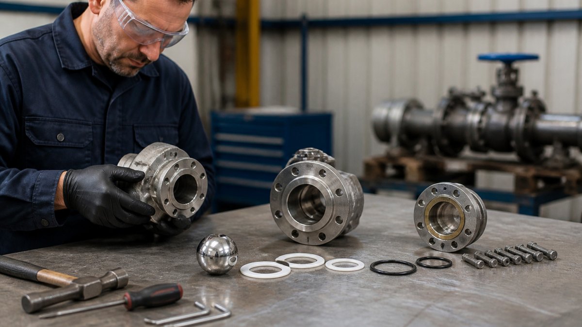
- Remove the bonnet bolts and lift the bonnet straight up
- Pull the stem and disc assembly, keeping it level
- Extract the old stem seal or packing with a seal removal tool
- Clean every component with a solvent compatible with the process fluid
- Inspect the seats, stem, and bore for scoring, pitting, or corrosion
- Measure bore and stem diameters against the manufacturer’s tolerances
Replace any component with visible damage. A cleaned valve body can still hide surface cracks, so consider dye penetrant testing on critical service valves.
Pneumatic Ball Valve Seal Replacement: Key Differences
Pneumatic ball valve seal replacement follows the same basic steps, but the actuator adds work. Disconnect the air supply and mark the actuator position before removal so you can restore the correct stroke. Ball valves also use soft seats, often PTFE or a reinforced polymer. These seats wear faster in abrasive or high-temperature service, so inspect them every maintenance interval rather than waiting for a leak.
Installing New Seals, Lapping Sealing Surfaces, and Torque Specifications
Seal installation is where most repairs succeed or fail, and the two failure drivers are almost always the same: a seal seated off-square, or a bonnet bolted down unevenly. Both are preventable with a disciplined sequence.
Seal installation mechanics
Lubricate the new seal only with the lubricant the seal and valve manufacturer specifies. A petroleum-based grease on an EPDM seal, for example, can cause swelling and premature failure, while silicone grease on a Viton seal in oxygen service is a fire hazard.
For packing-style stem seals, install rings one at a time and stagger the ring joints 90 degrees apart so the joints do not line up into a leak path. Seat each ring with the packing follower before adding the next.
Lapping sealing surfaces
Lapping restores the seat or disc face to a flat, scratch-free surface. Work a fine lapping compound, typically 320 to 600 grit for soft-seated valves, finer for metal seats, across the surface in a figure-eight pattern, rotating the component a quarter turn every few strokes to keep the cut even. Check progress with layout dye: a uniform gray contact pattern across the full seat face means the surface is true. Clean every trace of compound with solvent and a lint-free wipe before reassembly; leftover grit will scratch the new seal and start the failure cycle over.
Torque specifications and bolt patterns
Torque is where assembly errors masquerade as seal failures.
A common industrial pattern for a four-bolt bonnet is:
- Snug all bolts by hand in a star pattern (12 o’clock, 6, 9, 3).
- Torque to roughly 30% of final value in the same star pattern.
- Torque to roughly 60% of final value in the same pattern.
- Torque to 100% of final value in the same pattern, then make a final confirmation pass around the circle.
For eight-bolt flanges, work in a cross pattern that always tightens the bolt opposite the one just tightened, and repeat the staged percentages.
Use a calibrated torque wrench, and confirm the wrench’s calibration date before the job.
Watch out: Reusing a crushed or hardened gasket and torquing it to the original spec will not restore the seal, the gasket has already taken a set, and the flange will leak again within weeks.
The steps below summarise the torque sequence the article describes for a four-bolt bonnet.
| Step | Action | Load |
|---|---|---|
| 1 | Snug all bolts by hand in a star pattern | Hand tight |
| 2 | Torque in star pattern | About 30% of final value |
| 3 | Torque in same star pattern | About 60% of final value |
| 4 | Torque in same pattern, then confirmation pass | 100% of final value |
Repair Versus Replacement, Material Compatibility, and Root Cause Analysis
Repair is not always the right answer, and replacing a seal without understanding why it failed almost guarantees a repeat. This section covers the three decisions that separate a one-time fix from a recurring problem: whether to repair or replace, which seal material to specify, and what actually caused the failure.
Repair versus replacement
Repair is usually the right call when the body, bonnet, and stem are sound and the damage is confined to the seal, seat, or packing. Industry data from a 2026 valve repair seminar reported that repairing a valve rather than replacing it saved customers an average of 20% on one valve and more than 30% on two valves (Valve Magazine, Plant Turnarounds: The High-Stakes Decisions Behind Every Valve).
Material compatibility guide
Seal material selection is the single most overlooked cause of repeat failures. A seal that works in water can swell, crack, or extrude in solvent, steam, or caustic service. Match the seal to the process fluid, temperature, and pressure before ordering parts:
- PTFE and reinforced PTFE, broad chemical resistance across acids, bases, and solvents; good to roughly 500°F depending on grade; prone to cold flow and creep under high bolt load, so it needs proper gland support.
- Viton (FKM), excellent for hydrocarbons, oils, and fuels; good to roughly 400°F; poor in ketones, esters, and hot water/steam service.
- EPDM, excellent for water, steam, and many caustics; good to roughly 300°F; swells badly in petroleum oils and solvents.
- Nitrile (Buna-N), good for oils and fuels; limited temperature range (roughly 250°F); not suitable for ketones or strong acids.
- Graphite and flexible graphite, high-temperature stem packing for steam and hot process lines; handles extremes but needs controlled gland load.
Confirm the selection against the seal manufacturer’s chemical compatibility chart for the specific fluid concentration and temperature, not a generic table. A seal that is compatible at ambient temperature may fail at operating temperature.
Root cause analysis
If the same seal fails every six months, the part is not the problem, the process is. Work through the common failure modes:
- Thermal cycling, repeated heat-up and cool-down expands and contracts the stem and bonnet at different rates, loosening gland load and wearing the packing. Look for a pattern tied to startup and shutdown.
- Vibration and misalignment, a misaligned actuator or a bent stem side-loads the seal and wears it unevenly. Check stem runout and actuator alignment during inspection.
- Chemical attack, swelling, softening, or cracking of the seal points to an incompatible material, not a defective part.
- Over-torque and over-tightening, crushed packing or a distorted bonnet flange produces a leak that looks like seal failure but is an assembly error.
- Abrasive service, slurry or particulate media erodes seats and seals; these valves need shorter inspection intervals and harder seat materials.
Fugitive emissions compliance
For valves in volatile organic compound (VOC) or hazardous air pollutant (HAP) service, seal and packing selection can also be a regulatory question. Confirm the applicable fugitive-emissions requirement with the relevant regulator and your facility’s compliance team before specifying a replacement packing.
Watch out: Using a seal from a different valve design can look like a fit and still fail under pressure. Each valve design has its own maintenance requirements, so confirm the part number against the valve’s nameplate data and the manufacturer’s bill of materials before installation.
Testing for Leaks After Repair and Scheduling Your Next Valve Service
Never return a repaired valve to service without testing it. Run a low-pressure seat test first, then a full-pressure hydrostatic or pneumatic test according to the applicable standard.
Record the test results, torque values, and parts used in the maintenance log. That record makes the next service faster and shows the pattern of wear over time.
Plan the next service based on the operating conditions, not a fixed date alone. Valves in high-temperature or abrasive service need inspection more often than those in clean, moderate duty.
Frequently Asked Questions
How do you replace a seal in an industrial valve?
Start by isolating the line, depressurizing the valve, and locking out the actuator power source. Remove the bonnet or body bolts following the manufacturer’s sequence, extract the old seal and packing, and clean the sealing surfaces. Inspect the valve seat and stem for scoring. Install the new seal with the correct orientation, reassemble to the specified torque pattern, and pressure test before returning the valve to service. Always follow the valve manufacturer’s maintenance manual for the specific design.
What causes industrial valve seals to leak?
Common causes include wear and tear from cycling, corrosion, chemical incompatibility between the seal material and the process fluid, temperature extremes, improper installation, and over- or under-torqued bolts. Fugitive emissions often trace back to worn packing or stem seals. Root cause analysis helps determine whether the failure came from the seal material, the operating conditions, or the installation, so the same failure does not repeat.
Can a leaking ball valve seal be repaired?
In many cases, yes. Seat and seal kits can often restore a ball valve when the body and ball are still in good condition. Repair is often less costly than full replacement, depending on the valve’s condition. However, repair is not appropriate when the body, ball, or stem is damaged beyond specification. Confirm the decision against the manufacturer’s repair guidance.
How do you test a valve after replacing its seals?
Perform a pressure test at the rated test pressure defined by the valve standard and the manufacturer’s documentation, holding for the specified duration while monitoring for leakage. Check the stem packing and bonnet joint as well as the seat. Verify actuator operation through full stroke cycles. Document results, including torque values and test pressures, to support compliance records and future maintenance planning.


CREDIT APPLICATION
Please fill out our credit application for purchase orders and net terms. Download here

DISTRIBUTORS WANTED
Apply to become an official protected distributor. Click here to fill out our distributor application. (Online Form)

VALVE PRODUCT CATALOG
New! Download our 2018 product overview catalog or call us to request a copy. Click here to download (PDF)


