
Home »
Industrial Valve Automation Components List
Table of Contents
- What Is Industrial Valve Automation and Why Components Matter
- Valve Actuator Types: Pneumatic, Electric, and Hydraulic
- Solenoid Valves and Directional Control in Automation
- Valve Actuator Sizing: Matching Actuator to Valve Requirements
- Valve Positioner and Feedback Systems
- Electrical Connections, Wiring, and Control Signals
- Mounting, Interface Standards, and Fail-Safe Positioning
- How Valve Automation Components Work Together
- Frequently Asked Questions
Last Updated: October 12, 2026
What Is Industrial Valve Automation and Why Components Matter
Industrial valve automation transforms manual flow control into intelligent, responsive systems. Valtorc International has over 40 years of expertise in delivering high-quality, industrial-grade valve solutions, including automated valve packages.
Valve automation refers to the use of actuators, solenoid valves, sensors, and control systems to automatically open, close, or modulate industrial valves. The market reflects this shift: according to Future Market Insights’ industrial valve market analysis, butterfly valves alone represent 26.2% of the global industrial valve market, with the entire sector forecast to reach USD 134.8 billion by 2036.
A properly configured valve automation assembly eliminates human error, reduces response times from minutes to milliseconds, and ensures consistent process control across oil and gas refineries, chemical plants, water treatment facilities, and food and beverage production lines. But it only works when every component, from actuator to feedback sensor, is matched correctly to your valve and application.
This guide breaks down the essential industrial valve automation components list so you can select, size, and integrate the right parts for your operation.
Valve Actuator Types: Pneumatic, Electric, and Hydraulic
The actuator is your automation system’s muscle. It converts energy into mechanical motion that opens or closes your valve. The three primary types serve different industrial needs.
Pneumatic Actuators
Pneumatic actuators use compressed air to drive a piston or motor, creating linear or rotational motion. They’re fast, simple, and cost-effective.
Best for: High-speed switching, food and beverage plants, cleanroom environments where oil contamination is unacceptable, and facilities with existing compressed air infrastructure.
Key advantages:
- Rapid response times (often under 100 milliseconds)
- No electrical hazard in explosive atmospheres
- Low maintenance and simple installation
- Compact design for tight spaces
Pneumatic valve actuators direct pressurized air into a chamber; as pressure builds, the piston moves, rotating the valve stem or sliding the spool. Double-acting designs use air pressure on both sides of the piston, while single-acting designs rely on a spring return, making them inherently fail-safe. One limitation: pneumatic systems require a reliable compressed air supply, and any pressure drop reduces performance.
Electric Actuators
Electric actuators convert electrical current into rotational or linear motion via a motor and gearbox, offering precise control and seamless integration with digital control systems.
Best for: Processes requiring exact positioning, hazardous areas where pneumatic lines pose safety risks, remote monitoring applications, and systems needing proportional valve control.
Key advantages:
- Precise, repeatable positioning feedback
- Fully integrated with SCADA and PLC systems
- No external air or hydraulic supply needed
- Excellent for fail-to-position requirements
Electric actuators come in two main types: rotary (for ball and butterfly valves) and linear (for globe and gate valves). The trade-off: they consume more power than pneumatic ones and generate heat, so thermal management matters in high-cycle applications.
Hydraulic Actuators
Hydraulic actuators use pressurized fluid to generate force, delivering the highest power density of the three types for heavy-duty, high-pressure applications.
Best for: Subsea operations, extreme high-pressure systems (above 3,000 PSI), large industrial valves requiring massive force, and applications where response speed and power must coexist.
Key advantages:
- Highest force output per unit size
- Smooth, controllable motion even under extreme loads
- Excellent for fail-safe positioning with pilot valves
- Proven reliability in offshore and pipeline industries
Hydraulic systems demand rigorous maintenance. Fluid cleanliness, temperature control, and leak prevention are non-negotiable.
Solenoid Valves and Directional Control in Automation
A solenoid valve is an electrically controlled directional control valve that routes pressurized air or fluid to your actuator. Energizing the solenoid coil creates a magnetic field that shifts an internal spool, opening or closing ports.
Solenoid valves are the command center of pneumatic and hydraulic automation systems. They receive a control signal, typically 24V DC or 120V AC, and instantly switch flow direction, determining which port receives pressure and which vents.
Common solenoid valve configurations:
- 2/2 valves: on/off only (pilot valve applications)
- 3/2 valves: two-position control (single-acting actuators)
- 4/2 valves: four-position directional control (double-acting actuators)
- 4/3 valves: mid-position options for proportional control
Solenoid valves respond within 50-200 milliseconds, ideal for fast-switching applications. However, they require a clean, dry air or fluid supply to prevent coil fouling and spool stiction.
Valve Actuator Sizing: Matching Actuator to Valve Requirements
Undersized actuators stall under load. Oversized ones waste energy and create shock loads. Proper sizing is the difference between smooth operation and catastrophic failure.
To size your valve actuator, you need three critical specifications from your valve manufacturer:
1. Torque or Force Requirement
2. Pressure Rating
Your actuator must handle the maximum differential pressure across the valve.
3. Valve Port Size and Mounting Interface
Actuators mount directly to the valve via a standard interface. ISO 5211 defines the most common mounting pad sizes and stem connections.
The calculation is straightforward for pneumatic actuators:
Force (pounds) = Pressure (PSI) × Piston Area (square inches)
For a 4-inch pneumatic actuator at 80 PSI supply pressure, you generate roughly 1,000 pounds of torque. Compare this to your valve’s breakaway torque requirement.
Electric actuators are rated by torque output directly. A 100 ft-lbs electric actuator handles any valve requiring less than 100 ft-lbs of breakaway torque.
Valtorc International offers custom-engineered products, including automated valve packages, designed to exact specifications for maximum performance and longevity.
Valve Positioner and Feedback Systems
A valve positioner is a feedback controller that continuously adjusts actuator output to maintain the exact valve position you command. Without one, your valve only opens or closes fully; with one, it holds any intermediate position to match process demand.
Positioners receive a control signal (4-20 mA analog or digital) and compare it to the actual valve position, sending additional pressure or electrical current to the actuator until the valve reaches the target.
This feedback loop is essential for:
- Proportional flow control
- Tight process regulation
- Compensation for changing load conditions
- Accurate material blending in chemical plants
Position Sensors and Limit Switches
Position sensors measure where your valve is and report it back to your control system. Limit switches are simple on-off devices that confirm the valve reached fully open or fully closed; if the valve stalls partway, the limit switch fails to activate, triggering an alarm.
Common sensor types:
- Linear Variable Differential Transformer (LVDT): Outputs a proportional analog signal (4-20 mA) representing valve position. Highly accurate, works in harsh environments, no moving parts.
- Potentiometric sensors: A sliding contact on a resistor. Cost-effective but less durable in vibration-prone settings.
- Magnetostrictive sensors: Measure position using a magnetic pulse along a wire. Excellent linearity and repeatability.
Limit switches are typically reed switches or mechanical snap-action switches mounted to detect the actuator rod position at full open and full closed. They require no power and provide a simple binary output.
Proximity Sensors and Feedback Signals
Proximity sensors detect the actuator rod’s position without physical contact, ideal for harsh environments where mechanical switches would corrode or fail. Inductive sensors work with ferrous metals, detecting magnetic field changes as the rod approaches. Capacitive sensors detect any conductive or non-conductive material but are more sensitive to interference. Hall effect sensors respond to magnetic fields and are compact, durable, and often integrated into modern electric actuators.
All feedback signals, whether from a positioner, limit switch, or proximity sensor, feed back to your control system (PLC, DCS, or SCADA). This closes the loop: your system knows the actual valve state at all times.
Electrical Connections, Wiring, and Control Signals
Your actuator and solenoid valves need power and control signals. This is where electrical connection standards matter.
Operating voltage for solenoid valves is typically 24V DC (most common), 120V AC, or 240V AC. Electric actuators operate on 120V, 240V, or 480V three-phase power, depending on motor size.
Connectors must match your environment. DIN 43650 connectors are standard for solenoid valve coils. M12 connectors are common for sensors and actuators in modern plants. Hermaphroditic connectors ensure correct mating.
Cable routing follows NEC standards: shielded cable prevents electromagnetic interference between power lines and low-voltage control signals, and power and signal cables should be separated by at least 6 inches.
Control signals come in two types:
- Digital (on-off): The solenoid coil is either energized or de-energized. Simple, reliable, but limited to two states.
- Analog (proportional): A 4-20 mA signal commands the valve to any position between fully open and fully closed. Requires a proportional valve and positioner.
Your PLC or control system outputs these signals based on process conditions.
Wiring errors are common and costly. Always verify:
- Correct operating voltage (24V, 120V, 240V, 480V)
- Proper grounding and bonding
- Shielding on analog signal cables
- Overcurrent protection (fuses or breakers sized to component specs)
Mounting, Interface Standards, and Fail-Safe Positioning
Your actuator must physically attach to your valve. This is where interface standards come in.
ISO 5211 defines the mounting pad size and stem connection for rotary actuators on ball and butterfly valves, specifying pad sizes F03, F04, F05, F07, F10, and F12 (roughly 1 to 4 inches).
Fail-safe positioning determines what happens if power is lost or the system fails. This is critical in safety-critical applications.
- Fail-to-open: The valve opens if the actuator loses power (used for emergency pressure relief or dump valves).
- Fail-to-close: The valve closes if power is lost (used for isolation or shut-off valves).
- Fail-in-place: The valve holds its last position (used in modulating control).
Pneumatic actuators with spring returns are inherently fail-safe. A spring pushes the piston to a default position if air pressure is lost.
In hazardous areas (classified as Division 1 or 2 under the National Electrical Code), all electrical components must be rated for the specific hazard class and group (gas, vapor, dust, etc.).
How Valve Automation Components Work Together
An industrial valve automation assembly is a coordinated system. Each component plays a specific role.
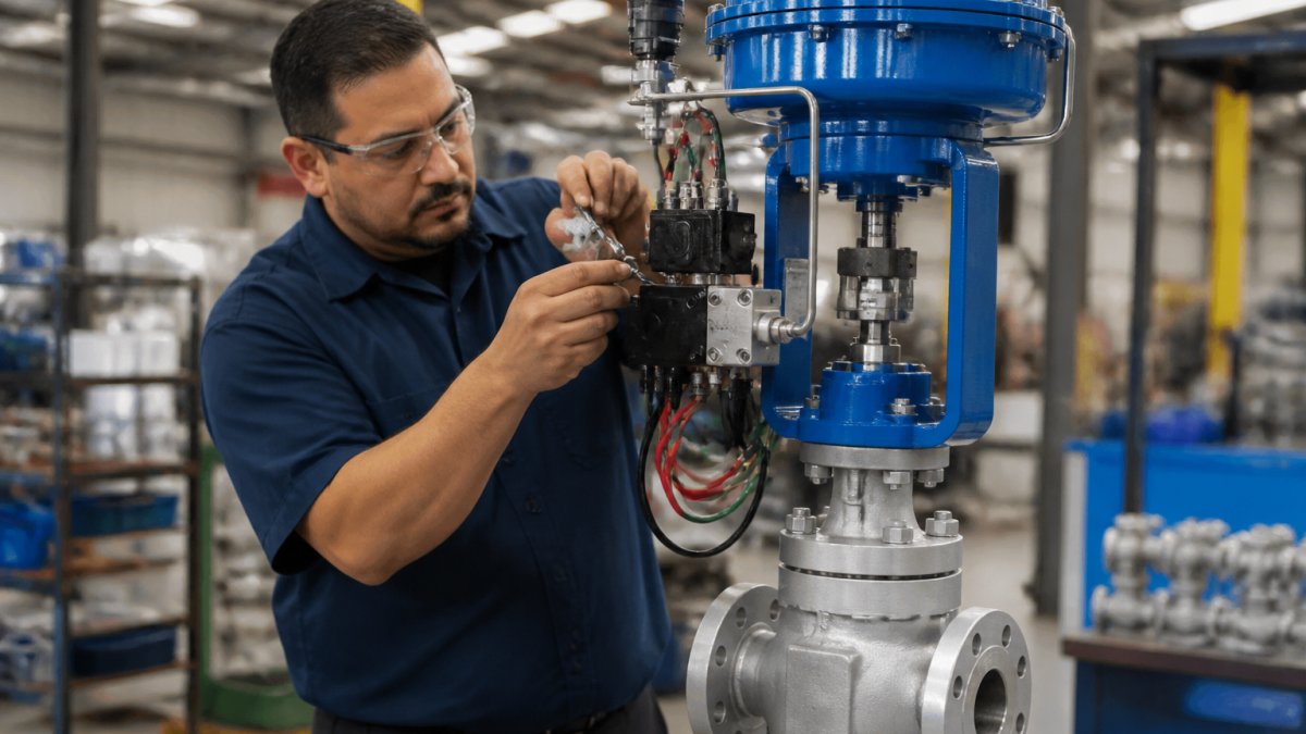
Here’s the sequence:
1. Your control system (PLC or DCS) detects a process need. A pressure transmitter reads 85 PSI, but setpoint is 100 PSI. The controller calculates an error and outputs a command.
**2.
3. Pressurized air or fluid flows to the actuator. The solenoid valve directs flow to the correct port of the actuator.
4. The actuator moves the valve stem. The piston or motor rotates or slides the valve open.
5. Feedback sensors report actual position and pressure. The position sensor outputs a signal proportional to actuator rod position.
**6.
7. The system reaches equilibrium. The valve settles at the exact position needed to maintain 100 PSI.
Every component, actuator, solenoid valve, positioner, sensor, and wiring, must be sized, selected, and installed correctly. A single mismatch cascades through the system.
Valtorc International empowers partners with reliable, custom-engineered products, including automated valve packages, designed to exact specifications for maximum performance and longevity.
Frequently Asked Questions
What are the main components of an industrial valve automation package?
An industrial valve automation package typically includes an actuator (pneumatic, electric, or hydraulic), a control valve, a solenoid valve for directional control, a valve positioner for precise positioning, limit switches or position sensors for feedback, electrical connectors and wiring, and mounting brackets. These components work together to automate valve operation, enable remote control, and provide real-time feedback on valve position and system status in industrial applications.
How do you match an actuator to a valve in an automation system?
Matching an actuator to a valve requires analyzing the valve’s torque or force requirements, operating pressure, response time needs, and environmental conditions. Valve actuator sizing depends on the valve’s size, type (ball, butterfly, gate), pressure differential, and flow rate. The actuator must deliver sufficient torque or force to overcome friction and pressure loads. Port size, connection type, and fail-safe positioning also determine compatibility. Consult the valve manufacturer’s specifications and the actuator’s torque/force rating to ensure proper sizing and reliable operation.
When does an automated valve need a positioner or limit switch?
A valve positioner is essential when precise, repeatable valve positioning is required, common in process control applications where flow rate or pressure must be maintained within tight tolerances. Limit switches are needed when you must confirm that a valve has fully opened or closed, or when fail-safe positioning is critical for safety. Position sensors and feedback signals provide continuous monitoring of valve position. In hazardous areas or safety-critical applications, both positioner and limit switches are often required to meet regulatory compliance and ensure safe, controlled operation.
What is the difference between pneumatic, electric, and hydraulic valve automation?
Pneumatic actuators use compressed air, are cost-effective, fast-acting, and ideal for on-off applications but less precise. Electric actuators offer precise control, modulation, and digital integration but require more power and maintenance. Hydraulic actuators deliver high force in compact sizes for heavy-duty, high-pressure applications but are more complex and require fluid management. Your choice depends on response time, precision requirements, available utilities, environmental protection rating, and operating pressure. Pneumatic suits rapid switching; electric suits process control; hydraulic suits extreme force demands.

CREDIT APPLICATION
Please fill out our credit application for purchase orders and net terms. Download here

DISTRIBUTORS WANTED
Apply to become an official protected distributor. Click here to fill out our distributor application. (Online Form)

VALVE PRODUCT CATALOG
New! Download our 2018 product overview catalog or call us to request a copy. Click here to download (PDF)


