
Home »
Electric Valve Actuator Troubleshooting: 7-Step Diagnostic Guide
Table of Contents
- Safety Precautions and Isolation Before Troubleshooting
- Step 1: Check Power Supply and Voltage
- Step 2: Inspect Electrical Connections and Terminal Blocks
- Step 3: Test Control Signal and Wiring for Faults
- Electric Valve Actuator Troubleshooting Checklist for Electrical Faults
- Step 4: Diagnose Motor Failure, Stalling, and Thermal Overload
- Electric Actuator Not Opening or Closing: Mechanical vs. Electrical Causes
- Step 5: How to Reset an Electric Valve Actuator
- Frequently Asked Questions
Last Updated: October 11, 2026
Safety Precautions and Isolation Before Troubleshooting
Before you touch any electric valve actuator, shut down the system safely. Electrical hazards are real. A live circuit can cause serious injury or death.
Always follow lockout-tagout (LOTO) procedures. This means:
- Switch off power at the main disconnect
- Lock the disconnect in the OFF position
- Tag it so others know not to restore power
- Verify power is actually off using a multimeter or voltage tester
- Wait for the system to depressurize completely
Never assume a valve is de-energized just because it’s not moving. Stored pressure in hydraulic or pneumatic lines can release suddenly. Vent pressure slowly using relief valves or bleed screws designed for that purpose.
Wear appropriate personal protective equipment. Safety glasses protect your eyes from debris. Gloves protect against sharp edges and electrical contact. Steel-toed boots are standard in industrial settings.
If the valve handles hazardous fluids, check the material safety data sheet (MSDS) before you begin. Some chemicals require special handling, ventilation, or protective gear. Never skip this step.
Ground yourself before handling electronic components. Static electricity can damage control boards and capacitors. Use an anti-static wrist strap connected to a grounded surface.
Never work on an electric valve actuator while the system is pressurized or powered. A sudden release of pressure or electrical surge can cause serious injury. Always isolate the actuator completely before beginning troubleshooting.
::: Proper isolation procedures serve as the essential foundation for safe commercial electrical troubleshooting throughout the entire facility infrastructure.
Step 1: Check Power Supply and Voltage
Power problems cause most electric valve actuator failures. Start here every time.
First, verify that power actually reaches the actuator. Use a multimeter set to AC or DC voltage mode, depending on your system. Touch the probes to the input terminals of the actuator. You should see the expected voltage. If you see zero volts, the power supply is not delivering electricity.
Check the voltage at the source panel first. If the panel shows correct voltage but the actuator terminals show zero, the problem is in the wiring or connections between them. Trace the circuit from the panel to the actuator. Look for loose wires, broken conduit, or damaged cable insulation.
Voltage drop across long wire runs can reduce the power reaching your actuator. Measure voltage at both ends of the run. If the voltage at the actuator is significantly lower than at the source, the wire gauge may be too small, or the wire may be damaged.
Check the power supply unit itself. Many actuators use a dedicated power supply module. These units can fail. Look for visible damage, burnt components, or indicator lights that show a fault condition. Some power supplies have a reset button. Press it and see if normal operation resumes.
Power supply problems often show up as intermittent actuator failures. The system works fine, then suddenly stops responding. This pattern usually means the power supply is delivering voltage inconsistently. Test it under load, measure voltage while the actuator is trying to operate, not just when idle.
Step 2: Inspect Electrical Connections and Terminal Blocks
Loose terminals are one of the most common causes of electric valve actuator trouble. A connection that looks tight can still have high resistance. High resistance generates heat, burns insulation, and eventually stops the flow of current.
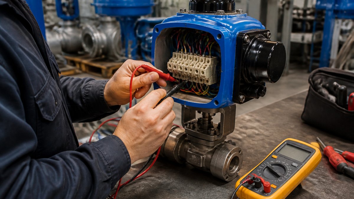
Examine every terminal block connection. Look for corrosion, discoloration, or burn marks around the terminals. Corrosion acts like an insulator and blocks current flow. Burn marks indicate heat damage from loose connections or arcing.
Use a screwdriver to tighten each terminal screw. Do not over-tighten, you want firm contact, not stripped threads. Many technicians use a torque screwdriver set to the manufacturer’s specification.
Pull gently on each wire after tightening. If the wire moves or pulls out, the connection was too loose. Tighten it again and test.
Check for damaged wire insulation. Cut, abraded, or melted insulation exposes bare copper. Bare wires touching each other or the actuator housing cause short circuits. Short circuits trip breakers and prevent operation.
Look for corrosion inside the terminal block. If the block is wet or exposed to salt spray or humidity, corrosion can spread inside where you cannot see it. Open the terminal block cover if possible.
Step 3: Test Control Signal and Wiring for Faults
The control signal tells the actuator to open or close. If the signal does not reach the actuator, nothing happens.
Trace the control wiring from the source to the actuator. Look for breaks, cuts, or pinches in the cable. Rodents, machinery, or careless handling can damage control wires. Even a small cut in the insulation can allow moisture in and cause intermittent failures.
Use a multimeter set to continuity mode. Disconnect the control wire at both ends. Touch one probe to each end of the wire. The multimeter should beep or show zero ohms, meaning the wire is intact. If it shows infinite resistance, the wire is broken.
Test the control signal voltage while the system is running. Set your multimeter to DC voltage. Touch the probes to the control signal terminals. You should see the expected signal voltage.
Many actuators use a feedback signal to report their position. This signal tells the controller whether the valve is open, closed, or somewhere in between. A broken feedback wire causes the controller to think the actuator is stuck. Check the feedback wiring using the same continuity test you used for the control signal.
Control signal problems often feel like the actuator is broken, but the real problem is communication. The actuator is waiting for a signal that never arrives. Always verify the signal is reaching the actuator before you conclude the actuator itself has failed.
Electric Valve Actuator Troubleshooting Checklist for Electrical Faults
Use this checklist to organize your troubleshooting work. Work through each item in order.
| Step | Check | Expected Result | If Failed |
|---|---|---|---|
| 1 | Power at source panel | Correct voltage (AC or DC) | Check power supply unit |
| 2 | Power at actuator terminals | Same as source panel | Inspect wiring and connections |
| 3 | Terminal block tightness | Wires do not pull out | Tighten all screws |
| 4 | Control signal present | Signal voltage appears | Check control wiring continuity |
| 5 | Feedback signal present | Position signal appears | Test feedback wire continuity |
| 6 | Actuator response | Valve moves when commanded | Proceed to mechanical checks |
Step 4: Diagnose Motor Failure, Stalling, and Thermal Overload
If power and control signals are good but the actuator still does not move, the motor itself may have failed.
Listen to the actuator when you command it to open or close. A healthy motor hums or makes a steady noise. A motor that is stuck or burned out makes no sound at all.
Feel the actuator housing. It should be warm but not hot. If it is too hot to touch, the motor is overheating.
Check for obstructions inside the valve. Debris, sediment, or corrosion can jam the valve stem. The actuator tries to move the stem but cannot. The motor stalls.
A blown fuse indicates a short circuit or severe overload. Look at the fuse holder. If the fuse is blackened or the wire inside is broken, the fuse has blown.
Inspect the power board or circuit board inside the actuator. Look for burnt components, discolored areas, or components that are cracked or missing. Burnt components indicate electrical failure. These boards usually cannot be repaired.
A capacitor that has failed can prevent the motor from starting. Capacitors store electrical energy to help the motor start smoothly. A failed capacitor shows as a bulging or leaking case.
Electric Actuator Not Opening or Closing: Mechanical vs. Electrical Causes
An actuator that receives power and control signals but still does not move the valve may have a mechanical problem, not an electrical one.
The difference matters. Electrical problems require electrical troubleshooting. Mechanical problems require different tools and fixes.
How to Distinguish Actuator Faults from Valve Faults
A seized or stuck valve is not the same as a failed actuator. The actuator may be working perfectly, but the valve stem will not turn.
Try this test: Command the actuator to open. Listen and feel for vibration. If the actuator vibrates or makes noise but the valve does not move, the valve is stuck, not the actuator.
Check the valve for corrosion or mineral buildup. Valves that sit unused for long periods can seize. Corrosion on the stem or inside the valve body prevents movement. A stuck valve requires mechanical cleaning or replacement. It does not require a new actuator.
Apply gentle pressure to the valve stem by hand. If you can move it slightly by hand but the actuator cannot, the valve requires more torque than the actuator can provide. This is a sizing problem. The actuator is too small for the valve. You need a larger actuator with higher operating torque.
Check the actuator’s travel limit. Some actuators have adjustable stops that limit how far they can rotate. If the stops are set incorrectly, the actuator reaches its limit before the valve fully opens or closes. Adjust the stops according to the manufacturer’s instructions.
Never force a stuck valve. Forcing it can damage the valve stem, the actuator gears, or both. If the valve will not move with normal actuator force, stop and investigate why. The problem is usually corrosion, debris, or incorrect sizing, not a broken actuator.
Step 5: How to Reset an Electric Valve Actuator
Many electric valve actuators have a manual reset button or a reset procedure. Resetting can clear temporary faults and restore normal operation.
Locate the reset button on your actuator. It is usually a small red or black button on the side or top of the housing.
Press and hold the reset button for 3 to 5 seconds. Some actuators require you to hold it longer. Release the button.
Power cycle the system. Switch off power at the main disconnect. Wait 10 seconds. Switch power back on.
If the actuator still does not respond after reset, the fault is not temporary. Return to the troubleshooting steps above and work through the electrical checks systematically.
Some actuators have a manual override. This allows you to move the valve by hand if the motor fails. The override is usually a wrench-flat or lever on the actuator output shaft.
Document what you find during troubleshooting. Note the voltage readings, any error codes or fault lights, the sounds the actuator made, and the temperature of the housing.
Electric valve actuator troubleshooting requires a systematic approach and proper safety discipline. Start with power and control signals. Move to mechanical checks only after you have ruled out electrical faults.
Frequently Asked Questions
What are the most common causes of electric valve actuator failure?
Power-supply problems account for approximately 40% of electric actuator failures, followed by control-signal issues, mechanical binding, motor burnout, and position feedback problems. Most failures stem from inadequate voltage, loose or corroded terminals, wiring faults, or mechanical resistance in the valve stem. Regular inspection of electrical connections and power supply can prevent the majority of these issues before they cause downtime.
How do I know if my electric valve actuator is bad versus the valve itself?
Isolate the actuator from the valve mechanically and apply power. If the actuator shaft rotates smoothly and the motor runs without stalling, the actuator is likely functional and the valve may be seized or obstructed. If the actuator does not rotate, runs intermittently, or stalls under light load, the fault is in the actuator, check power, wiring, and motor condition. Position feedback errors also indicate an actuator issue rather than a valve problem.
Can I reset an electric valve actuator myself, and what does that actually do?
Yes. A reset clears position-feedback errors and signal-hunting conditions by cycling power off for 10-15 seconds, then restoring it. This works when the actuator is electrically sound but stuck in a confused state. Reset does not fix power, wiring, or motor faults. After reset, verify the actuator responds to control signals and reaches full open and closed positions. If the problem recurs immediately, the underlying electrical or mechanical fault remains and requires diagnosis.
What should I check if my actuator runs but the valve does not move?
First, verify the actuator shaft rotates freely when powered and not under load. If it does, the coupling or drive mechanism between actuator and valve stem may be loose or broken. If the shaft does not rotate despite the motor running, the motor may be stalling due to mechanical resistance, inadequate torque, or internal damage. Check for seized valve stems, packing friction, and obstruction. Measure operating torque required versus the actuator’s rated capacity, if the valve requires more torque than the actuator can deliver, replacement or valve service is necessary.

CREDIT APPLICATION
Please fill out our credit application for purchase orders and net terms. Download here

DISTRIBUTORS WANTED
Apply to become an official protected distributor. Click here to fill out our distributor application. (Online Form)

VALVE PRODUCT CATALOG
New! Download our 2018 product overview catalog or call us to request a copy. Click here to download (PDF)


